In industrial lifting operations across Latin America—from construction sites in Mexico to mining operations in Chile and ports in Brazil—the lifting sling is only as strong as its connection points. A high-quality polyester sling with a WLL of 10 tons offers no protection if the shackle pin is undersized, the hook throat is deformed, or the connection angle compromises the entire lifting system.
Rigging hardware—shackles, hooks, and other connecting elements—forms the critical interface between the lifting sling and the load, or between the sling and the crane hook. Proper selection, connection, and inspection of these components are essential for safe and compliant lifting operations under ASME B30.9, EN 1492-1, EN 1492-2, and regional LatAm standards including Brazil NR-11, Mexico NOM-151, and Chile NCh 2245.
This guide provides a comprehensive framework for the safe use of lifting slings with shackles, hooks, and rigging hardware, covering correct connection practices, load angle considerations, and inspection criteria for hardware components.
1. Understanding Rigging Hardware Components
Shackles
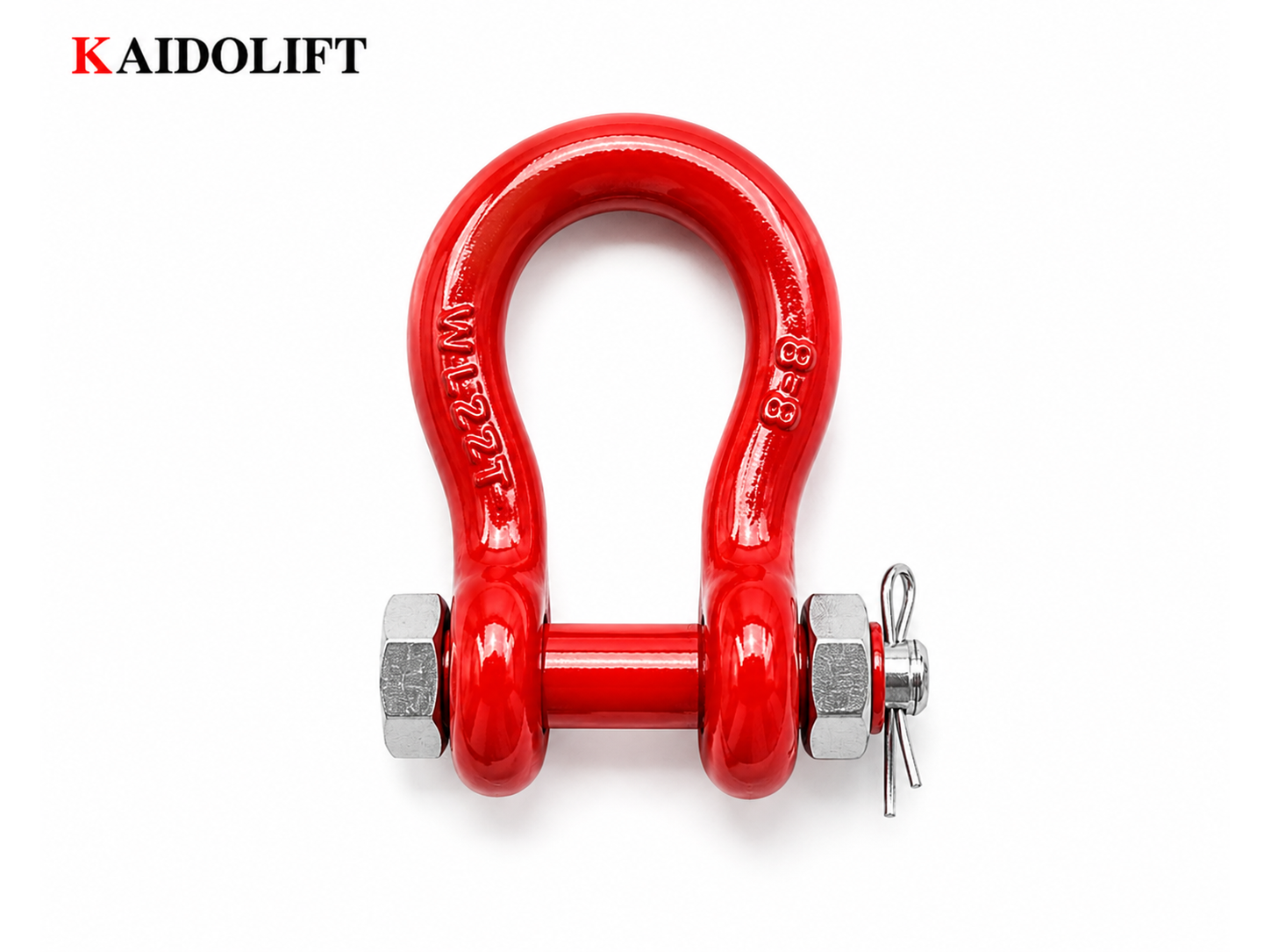
Shackles are U-shaped load-bearing connectors with a pin across the opening. They are the most common connection point between a sling and a load or between multiple sling legs.
Common Types:
| Shackle Type | Description | Best Application |
|---|---|---|
| Bow Shackle | Wider, rounder bow shape; larger working area | Multi-leg sling connections, loads requiring angular flexibility |
| Screw Pin Shackle | Threaded pin that screws into one leg | General-purpose lifting, quick connections |
| Bolt-Type Shackle | Pin secured with a nut and cotter pin | Permanent or semi-permanent installations |
| Clevis Shackle | Flat-sided, pin through both ears | Straight-line pulling applications |
Key Rating: Bow shackles are rated for loads applied at any angle to the bow’s centerline, making them significantly more versatile for multi-leg and basket hitch configurations.
Critical Advantage: Bow shackles feature a larger bow design that allows them to accept multiple sling legs or fittings. For applications involving angular loading, the bow shackle’s rounded shape reduces stress concentrations compared to D-shackles.
Hooks
Hooks are curved or angled devices used to connect slings to crane blocks, hoists, or load points.
Common Types:
| Hook Type | Description | Best Application |
|---|---|---|
| Crane Hook | Standard lifting hook on crane block | Primary crane-to-sling connection |
| Eye Hook | Hook with an eye for connection | Connecting to sling eyes or shackles |
| Grab Hook | Spring-loaded or latching hook | Quick connections, chain slings |
| Self-Locking Hook | Hook with automatic latch | Safety-critical applications requiring positive locking |
Critical Factor: The throat opening of a hook determines its capacity. The rated WLL applies when the load is centered in the hook saddle. Off-center loading reduces capacity.
Connecting Elements and Fittings
Additional hardware used in rigging systems includes:
- Master Rings/Links: Large rings used to connect multiple sling legs to a crane hook
- Eye Bolts: Threaded bolts with an eye for lifting point attachments to loads
- Turnbuckles: Adjustable tensioning devices for load alignment
- Swivels: Allow rotation of the load relative to the crane hook
Hardware Markings and Traceability
ASME B30.9 requires that all rigging hardware be clearly marked with the manufacturer’s identification and the rated load capacity. For shackles, the size and WLL must be visibly indicated on the bow, while hooks are marked on their body. The legible identification tag on your rigging hardware must be kept clean and readable.
2. Connection Principles: Sling to Shackle to Hook
Connecting Sling Eyes to Shackles
The connection between a sling eye and a shackle must respect the geometry of both components to avoid side loading and stress concentration.
Correct Practice:
- Align the sling eye with the shackle pin: The sling eye should lie flat against the shackle pin, not twisted or angled.
- Ensure the shackle pin seats fully: The pin should be fully threaded and properly torqued.
- Use the correct shackle size: The shackle bow must be large enough to accommodate the sling eye width without compression or deformation.
- Avoid point loading on the sling eye: The connection should distribute load across the full width of the sling eye.
Incorrect Practices (Avoid):
- Sling eye twisted relative to the shackle pin
- Sling eye compressed or crushed between shackle ears
- Shackle pin not fully seated
- Using an undersized shackle that forces the sling eye into a point-load condition
Connecting Slings to Hooks
The interface between a sling and a crane hook is critical. If the sling is positioned incorrectly in the hook saddle, the hook’s capacity is reduced.
Correct Practice:
- Place the sling in the hook saddle: The sling must sit in the deepest part of the hook curve (the saddle), never on the hook tip.
- Center the sling: The load should be centered in the hook saddle, not off to one side.
- Use the hook latch: Always engage the hook latch to prevent the sling from slipping out.
- Multiple slings: If using multiple slings on one hook, use a master link or large shackle to ensure proper load distribution across all legs.
Incorrect Practices (Avoid):
- Placing the sling on the hook tip (point loading)
- Allowing the sling to be off-center in the hook saddle
- Overloading the hook throat opening
- Using a hook without a functional latch
⚠️ CRITICAL NOTICE: ASME B30.9 requires that hooks not be bent, straightened, or repaired by welding. A hook with a throat opening greater than 15% of its original dimension must be taken out of service.
Matching Hardware to Sling Capacity
The WLL of the rigging hardware must equal or exceed the WLL of the sling being connected. A sling with a 5T capacity connected to a 3T shackle creates a weak point in the lifting system.
| System Component | WLL Requirement |
|---|---|
| Sling | 5 Tons |
| Shackle (Bow) | ≥5 Tons |
| Hook | ≥5 Tons |
| Master Link | ≥5 Tons |
🔧 MANDATORY PRACTICE: The weakest component in the lifting system determines the overall capacity. Always select hardware with a WLL that matches or exceeds the sling’s rated capacity.
3. Connection Angles and Load Transfer
How Hardware Connections Affect Load Capacity
When a sling is connected to a shackle or hook at an angle, the effective load on the hardware increases. The hardware’s WLL applies to straight-line loading—angular loading multiplies the force on the connection point.
The Tension Increase Formula:
For a single connection point where two sling legs meet at the hook or shackle:
Tension per Leg = Load Weight / Number of Legs × Cos(θ)
Where θ is the angle between the vertical axis and the sling leg.
Example:
- Load weight: 10 tons
- Number of legs: 2
- Angle from vertical: 45°
Tension per leg = 10T / (2 × Cos(45°)) = 10T / (2 × 0.707) = 10T / 1.414 = 7.07 Tons
This means each sling leg and its connection point (shackle/hook) must be rated for at least 7.07 tons, not simply 5 tons (10T ÷ 2).
Angle Limits for Hardware
Just as slings have angle limits, hardware connections have maximum angular limits:
| Angle from Vertical | Tension Increase Factor | Critical Consideration |
|---|---|---|
| 0° (Straight lift) | 1.00 | Full capacity available |
| 30° | 1.15 | Moderate increase, generally acceptable |
| 45° | 1.41 | Significant increase, requires capacity verification |
| 60° | 2.00 | Double the tension—caution required |
| >60° | >2.00 | Critical—avoid, alternative rigging required |
⚠️ CRITICAL NOTICE: If the angle from vertical exceeds 60°, the tension on each leg more than doubles. This drastically compromises the integrity of both the sling and the hardware connection. Re-rig the lift or use a spreader beam.
4. Common Connection Errors and Their Consequences
Error 1: Side Loading the Shackle or Hook
What It Is: Load is applied at an angle to the pin axis (shackle) or to the side of the hook saddle.
Consequence: Side loading can reduce the WLL of a shackle by up to 50% and can deform or break the hook.
Prevention: Always align the load with the pin axis (shackle) or center the load in the hook saddle. Use a bow shackle instead of a D-shackle for angular connections.
Error 2: Using an Undersized Shackle
What It Is: A shackle with a WLL below the sling’s WLL is used.
Consequence: The shackle becomes the weak point in the system. The lift fails at the shackle, not the sling.
Prevention: Verify that the shackle’s rated capacity matches or exceeds the sling’s WLL.
Error 3: Twisting the Sling Eye on the Shackle Pin
What It Is: The sling eye is twisted 90° or more relative to the shackle pin.
Consequence: The sling eye is subjected to point loading, reducing its effective strength. The shackle pin may be subjected to side loading.
Prevention: Ensure the sling eye lies flat against the shackle pin. Use a larger shackle if necessary.
Error 4: Overloading the Hook Throat Opening
What It Is: The hook throat opening is forced open by excessive load or the wrong lifting configuration.
Consequence: ASME B30.9 requires that hooks with a throat opening greater than 15% of the original dimension be removed from service.
Prevention: Ensure the load is centered in the hook saddle. Use a larger hook if the sling bundle is too wide for the throat opening.
Error 5: Mixed Hardware Types with Incompatible Shapes
What It Is: Connecting a D-shackle to a large bow, or a hook to a D-shackle at a tight angle.
Consequence: Point loading, stress concentration, and reduced capacity.
Prevention: Use hardware that is geometrically compatible. Bow shackles are preferred for angular connections.
5. Inspection and Maintenance of Rigging Hardware
Hardware components must be inspected regularly to ensure safe operation. ASME B30.9 sets out clear inspection criteria.
Pre-Use Inspection Checklist
Shackles:
- Check for cracks, corrosion, pitting, or deformation
- Verify threads are intact and the pin threads properly
- Ensure the pin is fully seated and not bent
- Check that the WLL markings are legible
- Inspect for heat damage or weld splatter
Hooks:
- Check the throat opening—if increased >15% of original, remove from service
- Inspect for cracks, deformation, or twisting
- Verify the latch is functional and not bent
- Check that the WLL markings are legible
- Inspect for wear or abrasion at the saddle point
Master Links and Fittings:
- Check for cracks, corrosion, or deformation
- Verify wear does not exceed 10% of original diameter
- Inspect for stress cracks or fatigue
- Ensure WLL markings are legible
Periodic Inspection
For hardware used in demanding environments (mining, offshore, heavy construction), periodic inspections should be conducted at monthly intervals. Document findings in the periodic rigging log.
Removal from Service Criteria
According to ASME B30.9, hardware must be removed from service immediately if:
- Visible cracks or stress fractures
- Excessive wear (wear exceeding 10% of original diameter)
- Deformation (bent, twisted, or stretched beyond tolerance)
- Corrosion or pitting that reduces cross-section by more than 10%
- Throat opening of hook increased >15% of original
- Missing or illegible WLL markings
- Heat damage or weld splatter burn marks
6. Regional Compliance: LatAm Standards
| Region | Standard | Key Requirement |
|---|---|---|
| Brazil | NR-11 (Annex 1) | Rigging hardware must be inspected annually with documented records; pins and shackles checked for wear and deformation |
| Mexico | NOM-151-SSA1 | Establishes safety requirements for lifting hardware; requires WLL markings and traceability |
| Chile | NCh 2245 | Defines technical requirements for rigging hardware; mandates periodic inspection and load testing |
| General | ASME B30.9 | Widely referenced standard; covers shackles, hooks, rings, and connecting elements |
Conclusion
The safe use of lifting slings with shackles, hooks, and rigging hardware requires attention to three critical areas:
- Compatibility: Hardware WLL must match or exceed sling WLL; geometric compatibility ensures proper load distribution
- Connection Quality: Correct positioning of sling eyes, shackle pins, and hook saddles prevents side loading and stress concentration
- Inspection Rigor: Regular pre-use and periodic inspection catches wear, deformation, and damage before failure occurs
For operations across Latin America, compliance with Brazil NR-11, Mexico NOM-151, and Chile NCh 2245 is essential. By matching hardware to sling capacity, respecting angular limits, and implementing rigorous inspection protocols, you can ensure that every connection point is as strong as the sling it connects.
📋 Need a Hardware-Sling Compatibility Quick-Reference Chart?
Download our LatAm-Compliant Rigging Hardware Selection Guide (PDF) —includes shackle-to-sling matching tables, hook capacity charts, and inspection checklists for Brazil (NR-11), Mexico (NOM-151), and Chile (NCh 2245).
[Download the Hardware Selection Guide No0w]