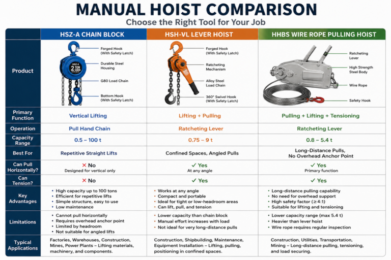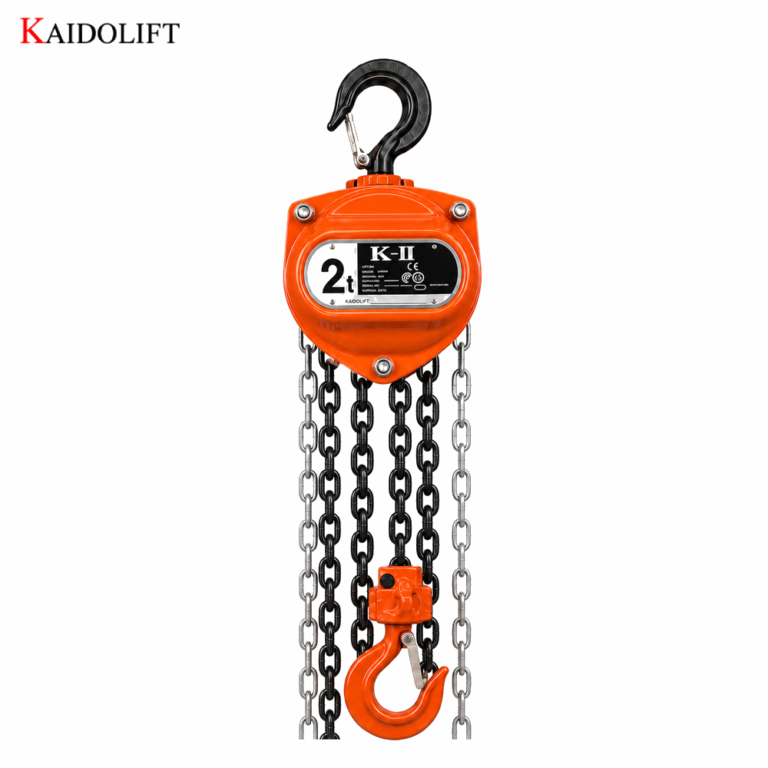
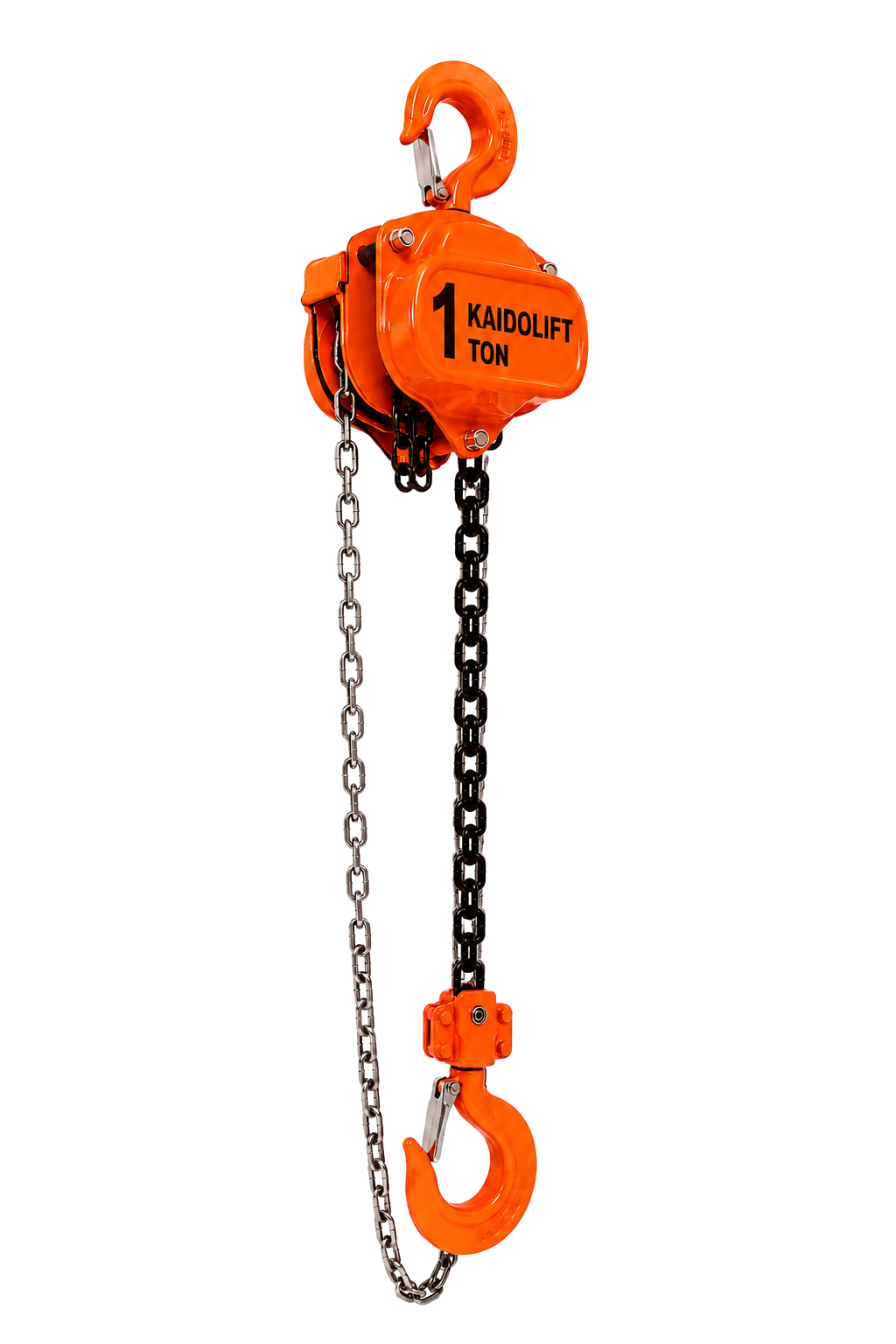
Chain Block is a core lightweight manual lifting equipment in industrial production, equipment maintenance, infrastructure hoisting, and warehousing and handling scenarios. It relies on human drive, The chain block is a high-performance lightweight manual lifting device widely adopted in industrial manufacturing, equipment overhaul, infrastructure hoisting, and warehouse logistics handling. Operating without power supply, it is perfectly adaptable to powerless, high-altitude, and confined working environments. With a compact integrated structure, stable load-bearing capacity, sensitive braking performance, and convenient manual operation, the equipment is extensively applied in machinery, mining, power engineering, construction, shipbuilding, and other industrial fields for conventional lifting and precise load positioning.
I. Overall Structural Composition and Core Modules
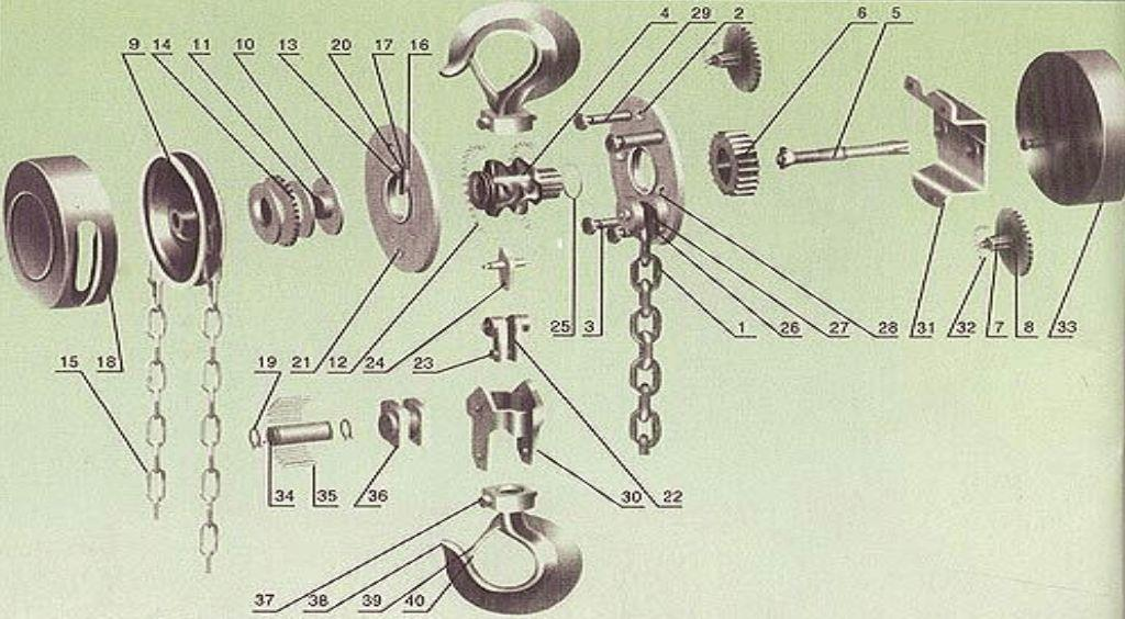
The chain block features a fully enclosed high-strength alloy steel shell structure. Its complete assembly consists of five core functional modules: drive system, transmission system, load-bearing system, self-locking braking system, and suspension fixing system. All structural components are precisely matched and cooperated to achieve labor-saving transmission and reliable safety braking. Major load-bearing parts are integrally forged with premium alloy steel, delivering excellent wear resistance, impact resistance, and structural stability for long-term industrial service.
1. Drive Module (Manual Power Input)
This module is composed of a manual hand chain and a hand chain wheel. The high-strength annular carbon steel hand chain acts as the manual force transmission medium. The toothed hand chain wheel is rigidly assembled with the five-tooth long driving shaft. Continuous and uniform pulling of the hand chain drives the synchronous rotation of the chain wheel, converting linear manual traction into rotational mechanical torque to provide stable power input for the entire equipment.
2. Transmission Module (Labor-Saving Core Mechanism)
The core labor-saving structure adopts a standard multi-stage planetary gear reduction transmission system, mainly including five-tooth long shafts, meshing plate gears, four-tooth short shafts, and splined lifting gears. Based on the deceleration principle of small gears driving large gears, the mechanism effectively amplifies input torque and reduces manual operating force, enabling heavy-load lifting with minimal manpower. The professional matched gear transmission ratio for different tonnage models ensures stable, efficient, and lossless power transmission under rated load conditions.
3. Braking Module (Safety Hovering Core)
Equipped with an industrial-grade ratchet friction disc one-way self-locking braking system, this module serves as the core safety protection unit of the chain block. It comprises a brake base, high-friction brake discs, ratchet wheel, elastic pawl, and brake compression spring. Featuring automatic load-adaptive locking performance, the system can instantly lock the transmission structure under load to prevent accidental falling of suspended loads, while ensuring flexible and unobstructed operation under no-load conditions, providing reliable safety guarantees for all lifting operations.
4. Load-Bearing Module (Load Execution Unit)
The load-bearing assembly includes load lifting chains, lifting sprockets, upper and lower lifting hooks, chain guide wheels, and chain storage grooves. The high-strength alloy load chain matches the lifting sprocket to output transmission torque and realize vertical lifting and lowering of loads. The integrally forged alloy steel hooks are equipped with elastic anti-drop clips, which can effectively prevent load decoupling during operation, ensuring safe and reliable load bearing throughout the working process.
5. Suspension Fixing Module
Consisting of an upper suspension hook, reinforced lifting beam, and thickened shell structure, this module is used for stably mounting and fixing the chain block on rigid bearing supports such as I-beams, fixed hangers, and construction scaffolds. It provides overall structural stability for the equipment and effectively avoids lateral offset, shaking, and unstable stress during hoisting operations.
II. Detailed Working Principle of Chain Block
The working mechanism of the chain block follows a complete closed-loop mechanical logic: manual power input → gear torque amplification → friction self-locking braking → controllable load lifting and hovering. It covers three standard working states: load lifting, static hovering, and load lowering, with precise mechanical linkage and independent functional logic to achieve fully controllable and safe manual lifting operation.
1. Load Lifting Principle
The operator pulls the hand chain clockwise at a uniform speed to drive the synchronous rotation of the hand chain wheel and coaxial five-tooth driving shaft. The driving shaft drives the bilateral plate gears for meshing operation, completes secondary deceleration through four-tooth short shafts, and finally drives the splined lifting gear to rotate at low speed and high torque.
During the lifting transmission process, the braking system operates in synchronous linkage. The rotating hand chain wheel squeezes the brake base and friction discs, clamps the ratchet wheel, and pushes open the elastic pawl to release braking restriction. The ratchet wheel and transmission main shaft operate synchronously without braking resistance. The lifting gear drives the sprocket to evenly retract the load chain, realizing stable and vertical lifting of heavy objects. The multi-stage gear reduction structure significantly amplifies manual torque to achieve labor-saving and efficient lifting.
2. Self-Locking Hovering Principle (Core Safety Mechanism)
When manual pulling stops and the operation is suspended, the external power input is cut off. The self-gravity of the suspended load generates reverse torque on the load chain and lifting sprocket, driving a slight reverse rotation trend of the main transmission shaft and triggering the automatic self-locking procedure of the braking system.
At this moment, the elastic pawl resets instantly under spring tension and is accurately clamped into the tooth groove of the ratchet wheel, locking the ratchet wheel firmly to prevent reverse rotation of the main shaft. Meanwhile, the friction discs fit tightly with the brake base, locking the entire transmission structure through static friction and completely fixing the load chain. This mechanism achieves zero sliding and zero falling of suspended loads during static hovering or intermittent operation, providing all-weather reliable load self-locking without any auxiliary manual braking operation.
3. Load Lowering Principle
The operator pulls the hand chain counterclockwise at a constant speed to drive reverse rotation of the hand chain wheel and synchronous rotation of the brake base. The friction discs are gradually separated to completely release the friction braking constraint. The ratchet wheel remains static under the limit of the pawl, avoiding synchronous reverse rotation and effectively preventing braking jamming and component wear.
The gear set operates reversely with the hand chain wheel, driving the lifting sprocket to slowly release the load chain and realize uniform and controllable lowering of heavy objects. The entire lowering process is manually controlled to eliminate free fall risks and ensure stable, low-speed, and safe load landing. Once the pulling force stops, the braking system resets and locks immediately to realize instant load hovering.
III. Industrial Standard Safety Operation Regulations
As a special manual lifting device, the chain block must be operated in strict compliance with national and industrial safety specifications for lifting machinery. The whole-process standardized management of pre-operation inspection, standardized operation, shutdown confirmation, and post-operation maintenance must be implemented to eliminate equipment failure, load falling, and personal safety accidents caused by irregular operations.
1. Pre-Operation Safety Inspection Requirements
(1) Personnel and site inspection: Only professionally trained and qualified personnel are permitted to operate the equipment; untrained staff and new operators are prohibited from independent operation. The working site shall be flat, open, and unobstructed, free of cross high-altitude operations and flammable, explosive, or corrosive materials. A safety isolation zone shall be delineated directly below the hoisting coverage area.
(2) Equipment appearance inspection: Check the shell for no deformation, cracking, rust or structural damage; confirm all fastening bolts are tightened in place. Inspect the upper and lower hooks for no cracks, permanent deformation or excessive wear, and verify the hook anti-drop spring clip is intact, flexible and effective.
(3) Chain condition inspection: Check the hand chain and load chain thoroughly to ensure no broken links, cracks, corrosion, deformation or excessive wear. The chain joints shall be firm without loosening, twisting or jamming, and the chain surface shall be clean without oil dirt, dust and sundries.
(4) No-load braking performance test: Perform repeated no-load lifting and lowering tests to verify sensitive, stable and reliable braking and self-locking performance. No slipping, chain sliding, abnormal noise or mechanical jamming is allowed during no-load operation.
(5) Suspension support inspection: The suspension bearing point must be rigid, stable and reliable, with a bearing capacity not less than 1.5 times the rated load of the chain block. Hanging the equipment on pipelines, cables, temporary supports and other unstable structures is strictly prohibited.
(6) Load confirmation: Accurately measure and confirm the weight of the lifting load. Overload operation, over-span inclination and over-height limit operation are strictly forbidden. Chain blocks of different tonnage grades must be used in strict accordance with their matched rated load parameters.
2. Standard On-Site Operation Specifications
(1) Safe standing posture: Operators shall stand on the lateral safe area of the load and maintain a sufficient safety distance. Standing directly under the suspended load, within the stress range of the load chain, or on the load lifting/lowering path is strictly prohibited to prevent falling object injuries.
(2) Standard force application: Pull the hand chain steadily, uniformly and vertically. Sudden pulling, violent jerking, shaking, diagonal pulling and lateral forced traction are prohibited, so as to avoid impact load causing gear tooth damage, chain fracture and sudden braking failure.
(3) Standard lifting posture: The load chain must bear force vertically at all times. Diagonal lifting, inclined lifting and horizontal traction of loads are forbidden. It is not allowed to drag or translate heavy objects with the chain block to prevent chain eccentric wear, hook deformation and equipment falling off.
(4) Load lifting control: Perform trial lifting before formal operation. Lift the load 100mm to 200mm and pause to inspect the stress condition of hooks, chains, suspension points and braking components. Formal lifting can only proceed after confirming no abnormalities. Keep uniform lifting and lowering speed without emergency stop, sudden rise or sudden fall during operation.
(5) Multi-person cooperative operation: For team operation with two or more operators, unified command and synchronous force application are mandatory. Disordered pulling and independent violent operation are prohibited to ensure consistent and stable working rhythm.
(6) Abnormality disposal: Immediately stop operation and slowly unload the load in case of chain jamming, braking slipping, abnormal mechanical noise or load shaking. Forced operation and faulty operation are strictly prohibited. Operation can only be resumed after complete troubleshooting and inspection confirmation.
3. Post-Operation Safety Closing Specifications
(1) After completing the lifting operation, stably land the load, completely remove the load stress from the chain block, retract the load chain in order and reset the hooks to the initial position.
(2) Clean the oil stains, dust and sundries on the equipment shell and chain surface, inspect the wear and working condition of chains and braking components, and apply appropriate lubrication to all movable parts.
(3) Store the chain block in a dry, ventilated and corrosion-free indoor environment. Long-term outdoor exposure, rain soaking and damp storage are forbidden to prevent component corrosion, aging and braking performance degradation.
(4) Complete operation records truthfully, register and report minor wear, abnormal noise and potential faults in a timely manner, and arrange professional maintenance and overhaul to eliminate hidden risks.
IV. Daily Maintenance and Regular Calibration Standards
1. Daily Maintenance
Clean the chain and shell thoroughly after each use to keep the equipment clean. Apply special lubricating grease to chains and gear movable parts regularly to reduce mechanical wear and ensure flexible transmission. Inspect the elasticity and effectiveness of hook anti-drop clips, brake springs and pawls daily to guarantee sensitive and reliable braking performance. Adopt moisture-proof, rust-proof and anti-extrusion measures during storage to avoid structural deformation and functional failure.
2. Regular Overhaul (Monthly / Quarterly)
Conduct monthly inspection on chain wear degree, hook deformation and bolt fastening status. Carry out quarterly disassembly and detailed inspection on gear wear, friction disc loss, spring elasticity and ratchet tooth integrity. Timely replace all over-worn, aging and failed accessories to ensure equipment performance meets industrial standards.
3. Annual Safety Calibration
Professional personnel shall conduct annual rated load tests and braking performance detection for the equipment and issue official safety calibration reports. Any unqualified equipment shall be immediately shut down and scrapped, and faulty chain blocks are strictly prohibited from being put into industrial production and operation.
V. Conclusion
The chain block adopts the core working principle of multi-stage gear labor-saving transmission + ratchet friction self-locking braking, realizing safe, stable and controllable manual light-duty hoisting operation. The self-locking braking system is the decisive core structure for ensuring hoisting safety. In industrial application, operators must strictly implement the management criteria of full pre-operation inspection, standardized operation, violation prohibition and periodic maintenance. By comprehensively controlling risks from equipment status, operating behaviors and working environment, all potential safety accidents such as load falling, equipment damage and personal injury can be effectively avoided, ensuring efficient, compliant and safe operation of industrial manual hoisting work.