In mining operations across Chile’s Atacama region, port terminals in Brazil’s Santos, and manufacturing plants throughout Mexico, electric hoist performance directly impacts cycle times and operational safety. This electric hoist speed testing method guide provides maintenance engineers and safety inspectors with a systematic approach to verifying lifting and traveling speeds against manufacturer specifications and international standards. Whether commissioning a new CD1/MD1 unit or conducting periodic performance audits, understanding proper measurement techniques ensures compliance with EN, ASME, and Latin American regulations such as NR-11 and NOM-151.
Why Speed Testing Matters: Performance, Safety & Compliance
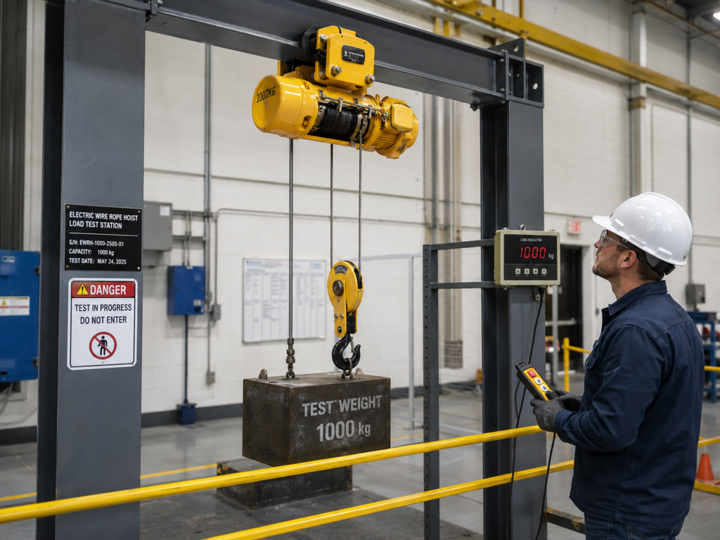
The Engineering Rationale
Electric hoist speed is not merely a convenience metric — it is a fundamental performance parameter that affects:
- Cycle time calculation: Accurate speed data enables precise material handling throughput planning
- Motor thermal loading: Deviations from rated speed indicate potential motor or gearbox issues
- Braking distance: Higher-than-specified speeds increase stopping distance, creating safety risks
- Load control: Inconsistent speed behavior suggests mechanical wear or electrical faults
Regulatory Drivers
Latin American safety regulations mandate periodic performance verification:
| Standard | Jurisdiction | Speed Testing Requirement |
|---|---|---|
| NR-11 | Brazil | Annual performance inspection including speed verification |
| NOM-151-STPS | Mexico | Periodic testing of lifting equipment operational parameters |
| NCh 2245 | Chile | Commissioning and periodic tests per manufacturer specifications |
| EN 14492-1 | International reference | Type testing and periodic inspection requirements |
| ASME B30.16 | International reference | Performance verification during load testing |
CRITICAL NOTICE: Operating a hoist with speed deviations exceeding ±10% of rated value indicates potential mechanical failure. Immediate inspection is required before continued operation.
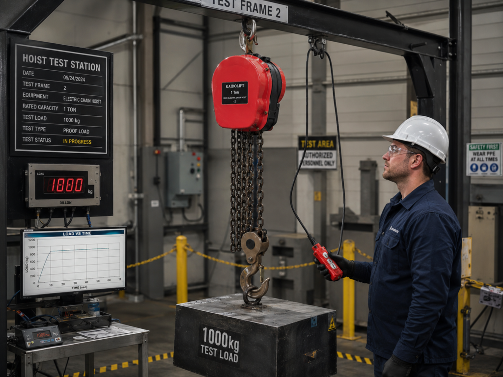
Standard Testing Procedures: No-Load & Loaded Conditions
Test 1: No-Load Lifting Speed Measurement
Objective: Verify motor and gearbox performance under unloaded conditions
Equipment Required:
- Digital tachometer or laser speed sensor
- Stopwatch (backup method)
- Measuring tape (minimum 10m)
- Test log sheet
Procedure:
- Setup: Mark a 5-meter vertical reference distance on the hoist runway structure
- Instrumentation: Mount the tachometer sensor on the drum shaft or use a laser sensor targeting the hook block
- Execution:
- Raise the empty hook through the marked distance
- Record the time taken (minimum 3 repetitions)
- Calculate average speed: v = distance / time
- Documentation: Record ambient temperature, supply voltage, and test results
Acceptance Criteria:
- No-load lifting speed should be within ±5% of manufacturer’s rated value
- Consistency across repetitions: variation < 2%
Test 2: Loaded Lifting Speed Measurement
Objective: Verify performance under rated load conditions
Procedure:
- Load preparation: Use certified test weights equal to 100% of rated capacity (WLL)
- Lift sequence:
- Raise the test load through minimum 3 meters of clear travel
- Record time for each repetition (minimum 3 cycles)
- Measure both lifting and lowering speeds
- Speed calculation:
v_loaded = L / t
Where:
- v_loaded = loaded lifting speed (m/min)
- L = measured lift distance (m)
- t = average time (min)
Critical Observation Points:
- Speed should remain stable throughout the lift
- No jerking or hesitation during acceleration
- Lowering speed should match or slightly exceed lifting speed
Test 3: Traveling Speed (Trolley/Crane Motion)
Objective: Verify horizontal motion speed for motorized trolleys
Procedure:
- Mark a 10-meter horizontal reference distance along the runway
- Run the trolley through the distance at normal operating speed
- Record time for minimum 3 passes in each direction
- Calculate average traveling speed
Typical Specifications:
| Hoist Capacity | Traveling Speed Range |
|---|---|
| 0.5T – 2T | 20 – 30 m/min |
| 3T – 5T | 15 – 25 m/min |
| 10T – 20T | 10 – 20 m/min |
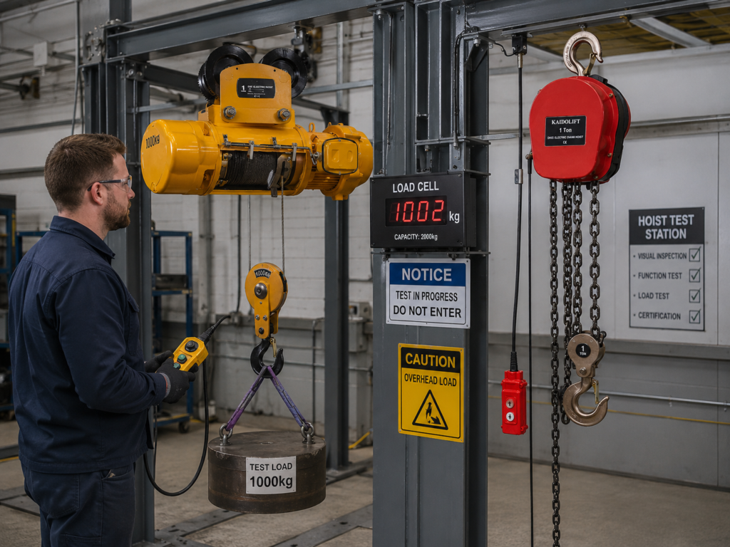
Speed Tolerance & Acceptance Criteria
Manufacturer Specifications vs. Field Measurements
All speed measurements must be compared against the manufacturer’s nameplate data or technical documentation. Acceptable tolerances are:
| Condition | Lifting Speed Tolerance | Traveling Speed Tolerance |
|---|---|---|
| No-load | ±5% of rated | ±5% of rated |
| Rated load | ±10% of rated | ±10% of rated |
| Overload test (125%) | Not specified (measure only) | Not specified |
Root Cause Analysis for Speed Deviations
When measurements fall outside acceptable ranges, systematic diagnosis is required:
Speed Lower Than Specified:
- Voltage drop at motor terminals (>5% indicates undersized supply cables)
- Worn gearbox bearings increasing friction
- Brake partially engaged (dragging)
- Overloaded condition (verify actual load vs. rated capacity)
Speed Higher Than Specified:
- Incorrect motor winding connection (if dual-speed)
- Gearbox internal damage (gear tooth failure)
- Load lighter than assumed (verify with calibrated scale)
Inconsistent Speed:
- Loose electrical connections causing intermittent contact
- Contactor wear creating voltage fluctuations
- Mechanical binding in drum bearings or rope guide
🔧 MANDATORY PRACTICE: If speed deviation exceeds ±10%, remove the hoist from service immediately. Tag-out and conduct a full mechanical inspection before returning to operation.
Field Testing Equipment & Best Practices
Recommended Instrumentation
| Equipment | Specification | Application |
|---|---|---|
| Digital tachometer | 0-10,000 RPM, ±0.05% accuracy | Drum shaft speed measurement |
| Laser speed sensor | Non-contact, 0.1 m/s resolution | Hook/block speed verification |
| Clamp-on ammeter | 0-100A AC, true RMS | Motor current during speed test |
| Voltage analyzer | Records voltage sag during starts | Supply quality assessment |
| Calibrated weights | ±1% accuracy, traceable to national standards | Load testing |
Environmental Considerations
Speed measurements are affected by environmental factors:
- Temperature: Motor resistance increases with temperature, potentially reducing speed by 2-3% at 40°C ambient
- Altitude: Above 1000m, motor cooling efficiency decreases; derating may apply
- Humidity: High humidity (>80% RH) can affect electrical contact resistance
Documentation Requirements
Every speed test must be documented with:
- Hoist identification (model, serial number, capacity)
- Test date and inspector name
- Ambient conditions (temperature, humidity)
- Supply voltage measured at motor terminals
- Test results (minimum 3 repetitions per condition)
- Comparison against rated values
- Pass/fail determination
- Corrective actions required (if any)
CRITICAL RULE: Retain speed test records for minimum 5 years or the life of the equipment, whichever is longer. These records demonstrate regulatory compliance and support warranty claims.
Conclusion
Systematic speed testing of electric hoists is not merely a regulatory obligation — it is a fundamental maintenance practice that ensures operational safety, predictable cycle times, and early detection of mechanical degradation. By following standardized procedures for no-load and loaded speed measurements, maintenance teams in Latin American industries can verify compliance with NR-11, NOM-151, and international standards while maximizing equipment uptime. The key is consistency: regular testing with proper instrumentation creates a performance baseline that makes deviations immediately apparent.