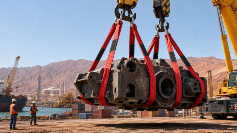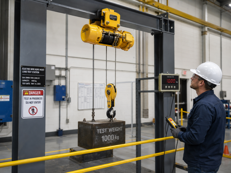
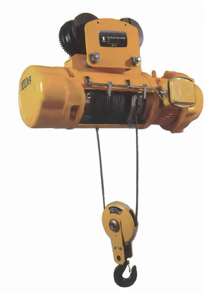
When you see a CD1 or MD1 electric hoist working on a construction site in Mexico City or a mining facility in Antofagasta, what you’re witnessing is decades of refined mechanical engineering distilled into a compact lifting solution. This CD1 MD1 electric hoist technical analysis breaks down the engineering decisions that make these machines reliable workhorses — from the conical rotor motor’s self-braking principle to the three-stage gearbox’s load distribution strategy. Understanding these design fundamentals helps maintenance teams troubleshoot faster and procurement engineers specify with confidence.
The Conical Rotor Motor: Self-Braking Through Magnetic Physics
How It Works
Unlike conventional motors that require a separate mechanical brake, the CD1/MD1 uses a conical rotor asynchronous motor where braking is achieved through electromagnetic principles:
- Rotor geometry: The rotor is shaped as a truncated cone, not a cylinder
- Magnetic pull: When energized, the stator’s magnetic field creates axial force that pulls the conical rotor toward the stator center
- Brake release: This axial movement compresses a spring-loaded brake disc, disengaging the brake
- Automatic engagement: When power is cut, the spring force pushes the conical rotor back, instantly engaging the brake
This design eliminates the need for external brake components, reducing both maintenance points and failure modes.
Technical Specifications
| Parameter | Specification | Engineering Significance |
|---|---|---|
| Duty Cycle | 25% (S3 intermittent) | Optimized for frequent start-stop cycles typical in material handling |
| Insulation Class | B (130°C) or F (155°C) | Withstands thermal stress from repeated starts |
| Protection Rating | IP44 / IP54 | Dust and splash resistance for industrial environments |
| Starting Torque | High (2.5× rated torque typical) | Ensures reliable load lifting from standstill |
CRITICAL NOTICE: The conical rotor brake is wear-dependent. Inspect brake disc thickness and spring tension every 500 operating hours. A worn brake disc can cause load drift — a serious safety hazard.
Three-Stage Helical Gearbox: Load Distribution Strategy
Gear Train Architecture
The reducer employs a three-stage fixed-axis helical gear configuration:
- Stage 1 (High-speed): Input from motor, highest RPM, lowest torque
- Stage 2 (Intermediate): Speed reduction continues, torque multiplication begins
- Stage 3 (Low-speed): Final output to drum, maximum torque, minimum RPM
Material Science Decisions
- Gear material: Alloy steel (20CrMnTi or equivalent) with case hardening
- Heat treatment: Carburizing to 58-62 HRC surface hardness, 30-35 HRC core
- Tooth profile: Helical (not spur) for smoother engagement and higher load capacity
- Housing: Grey cast iron (HT200/HT250) for vibration dampening and structural rigidity
The helical gear design provides two key advantages over spur gears:
- Gradual tooth engagement: Reduces impact loads and noise
- Higher contact ratio: Multiple teeth share the load simultaneously
Modular Design Philosophy
The gearbox is engineered as a self-contained module:
- Sealed housing prevents contamination ingress
- Pre-lubricated with synthetic gear oil (ISO VG 220 or equivalent)
- Mounting interface standardized for rapid replacement
- No field disassembly required for routine maintenance
This modularity means a failed gearbox can be swapped in under 2 hours, minimizing equipment downtime.
Wire Rope System: Fatigue Life Engineering
GB1102-74 (6×37+1) Construction
The hoist uses a specific wire rope configuration optimized for hoisting applications:
- 6 strands: Provides flexibility while maintaining strength
- 37 wires per strand: Fine wire diameter distributes bending stress
- Fiber core (FC): Acts as a cushion between strands, improving fatigue life
Why This Construction Matters
Compared to simpler 6×19 construction:
| Parameter | 6×19 | 6×37+1 |
|---|---|---|
| Flexibility | Moderate | High |
| Bending fatigue resistance | Good | Excellent |
| Abrasion resistance | Excellent | Good |
| Ideal application | Static loads | Dynamic hoisting |
For electric hoists with frequent drum wrapping/unwrapping, the 6×37+1 construction provides superior service life despite slightly lower abrasion resistance.
Inspection Critical Points
- Broken wires: >3 broken wires in one rope lay = immediate replacement
- Diameter reduction: >6% reduction from nominal = replace
- Corrosion: Visible pitting or rust residue = replace
- Kinking or bird-caging: Any deformation = replace immediately
Control System: Layered Safety Architecture
Electrical Protection Hierarchy
The control box implements multiple redundant safety layers:
- Main circuit breaker: Overcurrent and short-circuit protection
- Phase sequence relay: Prevents reverse operation from incorrect wiring
- Upper limit switch: Cuts lift circuit at maximum height
- Lower limit switch: Prevents over-lowering and rope damage
- Emergency stop: Direct main circuit interruption
Limit Switch Design
The “fire-proof” limit switches (断火限位器) use a specific design principle:
- Cam-actuated: Triggered by drum rotation, not rope position
- Positive-break contacts: Physically separate when activated
- Fail-safe: Spring-return to safe state if mechanism fails
MANDATORY PRACTICE: Test both upper and lower limit switches daily before operation. A stuck limit switch can cause over-travel, leading to rope damage or drum collision.
MD1 Dual-Speed: Precision Through Motor Design
How Dual Speed Is Achieved
The MD1 model achieves two speeds without external VFDs or mechanical gearboxes:
- Dual-winding motor: Separate windings for normal and slow speeds
- Pole changing: Different pole counts (typically 4-pole for normal, 24-pole for slow)
- Speed ratio: Approximately 10:1 (normal:slow)
Application Benefits
The slow speed (typically 0.8 m/min vs 8 m/min normal) enables:
- Mold positioning: Precise alignment in injection molding operations
- Load spotting: Fine placement on assembly fixtures
- Maintenance access: Controlled lowering for equipment servicing
Conclusion
The CD1/MD1 electric hoist represents a mature engineering solution where every component — from the conical rotor’s self-braking principle to the modular gearbox design — serves a specific functional purpose. Understanding these design fundamentals enables maintenance teams to diagnose issues faster, specify replacement parts accurately, and implement preventive maintenance strategies that maximize service life. For Latin American operations facing harsh environmental conditions, this engineering robustness translates directly into operational reliability.
🔧 Want deeper technical documentation?
Request our CD1/MD1 Maintenance Manual & Troubleshooting Flowchart — includes exploded diagrams, torque specifications, and fault diagnosis trees.